Product Description
Detailed Images
*Detailed Images of China Industrial gearbox manufacturers industrial gearboxes speed reducers
Different Mounting Postion of China Industrial gearbox manufacturers industrial gearboxes speed reducers
Product Description
Excellent Features of China Industrial gearbox manufacturers industrial gearboxes speed reducers
– FR, FK, FF series helical gearbox are characterised by compact structure, light weight, large torque and excellent performance;
– As a new reduing transimission system, it’s advantaged in design and manufacture on the basis of the modulized conbination, which can meet client’s requirement on connection and installation;
– Made of rib-reinforced rigid case and premium alloy-steel gear which is hardened by carbon penetration and grinned precisely;
– Stable running, low noise, large in load, low in consumption, efficient in transmission, low in temperature rise, and long in service life;
– The mounting styles are footing, flange, torque arm and so on. The output style are shaft, hollow shaft, the alpine and shrink disc are for choice.
– Input style: compact with motor, AM adapter for IEC or NEMA motor, AD CHINAMFG shaft input.
Related Products
FK Gearbox with Motor
Worm Gear Reducer
Cast Iron Worm Gearbox
Shaft Mounted Gearbox
Round Type Shaft Mounted Gearbox
Inch Size Shaft Mounted Reducer
Packing & Delivery
Packing Images of Helical Bevel Gearing Gearbox Speed Reducer
Inner Packing: PP bag with carton;
Outer Packing: Carton boxes and wooden case;
Shipment: 20-30 days CHINAMFG receiving the deposit.
About Us
CHINAMFG GROUP is the first and largest worm gearbox manufacturer in China, established in 1976, specialising in the production of a wide variety of transmission machinery. With more than 40 years experience in the industry, our assets now total 117.2 million dollars, and we have 2 subsidiary companies, 8 holding companies, and 12 joint-stock companies.
We can produce 400,000 units of worm gearboxes, 100,000 units of gear reducers, 50,000 units of other speed reducers, 150,000 units of flexible couplings, and 100,000 units of speed-reducer accessories every year.
70% of our products have been exported to 40 more countries, and our customers come from Italy, Germany, USA, Canada, Spain, UK, India, Mexico, Brazil, Argentina, Turkey, Singapore and other main industrial countries. 30% of them are OEM made for direct manufacturers of other products.
/* January 22, 2571 19:08:37 */!function(){function s(e,r){var a,o={};try{e&&e.split(“,”).forEach(function(e,t){e&&(a=e.match(/(.*?):(.*)$/))&&1
| Application: | Machinery, Agricultural Machinery |
|---|---|
| Hardness: | Hardened Tooth Surface |
| Installation: | Horizontal Type |
| Layout: | in-Line |
| Gear Shape: | Cylindrical Gear |
| Step: | Double-Step |
| Customization: |
Available
| Customized Request |
|---|
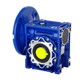
How to Install and Align a Worm Reducer Properly
Proper installation and alignment of a worm reducer are crucial for ensuring optimal performance and longevity. Follow these steps to install and align a worm reducer:
- Preparation: Gather all the necessary tools, equipment, and safety gear before starting the installation process.
- Positioning: Place the worm reducer in the desired location, ensuring that it is securely mounted to a stable surface. Use appropriate fasteners and mounting brackets as needed.
- Shaft Alignment: Check the alignment of the input and output shafts. Use precision measurement tools to ensure that the shafts are parallel and in line with each other.
- Base Plate Alignment: Align the base plate of the reducer with the foundation or mounting surface. Ensure that the base plate is level and properly aligned before securing it in place.
- Bolt Tightening: Gradually and evenly tighten the mounting bolts to the manufacturer’s specifications. This helps ensure proper contact between the reducer and the mounting surface.
- Check for Clearance: Verify that there is enough clearance for any rotating components or parts that may move during operation. Avoid any interference that could cause damage or performance issues.
- Lubrication: Apply the recommended lubricant to the worm reducer according to the manufacturer’s guidelines. Proper lubrication is essential for smooth operation and reducing friction.
- Alignment Testing: After installation, run the worm reducer briefly without a load to check for any unusual noises, vibrations, or misalignment issues.
- Load Testing: Gradually introduce the intended load to the worm reducer and monitor its performance. Ensure that the reducer operates smoothly and efficiently under the load conditions.
It’s important to refer to the manufacturer’s installation guidelines and specifications for your specific worm reducer model. Proper installation and alignment will contribute to the gearbox’s reliability, efficiency, and overall functionality.
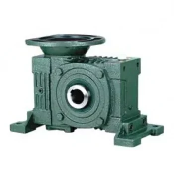
Materials Used for Worm Gears
Worm gears are manufactured using a variety of materials to meet different application requirements. Some commonly used materials for worm gears include:
- Steel: Steel is a popular choice for worm gears due to its strength, durability, and wear resistance. It can handle heavy loads and is often used in industrial applications.
- Bronze: Bronze offers good lubricity and is commonly used for the worm gear (worm) component. It provides effective wear resistance and works well in applications where quiet operation is essential.
- Cast Iron: Cast iron is known for its high strength and durability. It’s often used for worm gears in applications where shock loads or heavy-duty conditions are expected.
- Aluminum: Aluminum worm gears are lightweight and corrosion-resistant, making them suitable for applications where weight reduction is important.
- Plastic: Some worm gears are made from plastic materials such as nylon or acetal. These materials are often chosen for their self-lubricating properties and quiet operation.
- Composite Materials: Composite materials can offer a combination of properties, such as lightweight construction and corrosion resistance. They can be suitable for specific applications.
The choice of material depends on factors such as the application’s load, speed, operating environment, and required performance characteristics. It’s important to consider these factors when selecting the appropriate material for worm gears to ensure optimal performance and longevity.
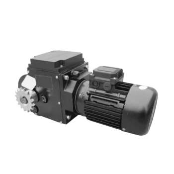
Lubrication Requirements for a Worm Gearbox
Lubrication is crucial for maintaining the performance and longevity of a worm gearbox. Here are the key considerations for lubricating a worm gearbox:
- Type of Lubricant: Use a high-quality, high-viscosity lubricant specifically designed for worm gearboxes. Worm gearboxes require lubricants with additives that provide proper lubrication and prevent wear.
- Lubrication Interval: Follow the manufacturer’s recommendations for lubrication intervals. Regularly check the gearbox’s temperature and oil condition to determine the optimal frequency of lubrication.
- Oil Level: Maintain the proper oil level to ensure effective lubrication. Too little oil can lead to insufficient lubrication, while too much oil can cause overheating and foaming.
- Lubrication Points: Identify all the lubrication points on the gearbox, including the worm and wheel gear surfaces. Apply the lubricant evenly to ensure complete coverage.
- Temperature: Consider the operating temperature of the gearbox. Some lubricants have temperature limits, and extreme temperatures can affect lubricant viscosity and performance.
- Cleanliness: Keep the gearbox and the surrounding area clean to prevent contaminants from entering the lubricant. Use proper filtration and seals to maintain a clean environment.
- Monitoring: Regularly monitor the gearbox’s temperature, noise level, and vibration to detect any signs of inadequate lubrication or other issues.
Proper lubrication will reduce friction, wear, and heat generation, ensuring smooth and efficient operation of the worm gearbox. Always refer to the manufacturer’s guidelines for lubrication specifications and intervals.


editor by CX 2024-03-28
China factory Nmrv 050 Gearbox Gear Box Wheel Speed Reducer Jack Worm Planetary Helical Bevel Steering Gear Drive Worm Manufacturer Industrial Worm Nmrv 050 Gearbox gearbox design
Product Description
NMRV 050 Gearbox Gear Box Wheel Speed Reducer Jack Worm Planetary Helical Bevel Steering Gear Drive Worm Manufacturer Industrial Worm NMRV 050 Gearbox
Application of NMRV 050 Gearbox
NMRV 050 gearboxes are a type of worm gear reducer that is used in a wide variety of applications. They are typically used in applications where high torque and low speed are required. Some common applications for NMRV 050 gearboxes include:
- Conveyors: NMRV 050 gearboxes are used to power conveyors, which are used to transport materials in a variety of industries, such as manufacturing, food processing, and logistics.
- Pumps: NMRV 050 gearboxes are used to power pumps, which are used to move fluids in a variety of applications, such as water treatment, wastewater treatment, and oil and gas production.
- Fans: NMRV 050 gearboxes are used to power fans, which are used to circulate air in a variety of applications, such as heating, ventilating, and air conditioning (HVAC).
- Actuators: NMRV 050 gearboxes are used to power actuators, which are used to move objects in a variety of applications, such as robotics, automation, and aerospace.
- Elevators: NMRV 050 gearboxes are used to power elevators, which are used to transport people and goods between different floors of a building.
- Security gates: NMRV 050 gearboxes are used to power security gates, which are used to control access to a building or area.
- Worm drive saws: NMRV 050 gearboxes are used to power worm drive saws, which are used to cut wood, metal, and other materials.
NMRV 050 gearboxes offer a number of advantages over other types of gear reducers, including:
- High torque: NMRV 050 gearboxes can generate high torque, which makes them ideal for applications where heavy loads need to be moved.
- Low speed: NMRV 050 gearboxes operate at low speeds, which makes them ideal for applications where smooth and controlled movement is required.
- Compact size: NMRV 050 gearboxes are typically smaller than other types of gear reducers, which makes them ideal for applications where space is limited.
- Low maintenance: NMRV 050 gearboxes require very little maintenance, which makes them a cost-effective choice for many applications.
Here are some of the limitations of NMRV 050 gearboxes:
- Low efficiency: NMRV 050 gearboxes are not as efficient as other types of gear reducers, which can lead to increased energy costs.
- High noise levels: NMRV 050 gearboxes can be noisy, which can be a concern in some applications.
- High maintenance costs: NMRV 050 gearboxes require more frequent maintenance than other types of gear reducers, which can increase overall costs.
Despite these limitations, NMRV 050 gearboxes remain a popular choice for a wide variety of applications due to their high torque and low speed capabilities.
/* January 22, 2571 19:08:37 */!function(){function s(e,r){var a,o={};try{e&&e.split(“,”).forEach(function(e,t){e&&(a=e.match(/(.*?):(.*)$/))&&1
| Application: | Motor, Electric Cars, Motorcycle, Machinery, Marine, Agricultural Machinery, Car |
|---|---|
| Function: | Distribution Power, Clutch, Change Drive Torque, Change Drive Direction, Speed Changing, Speed Reduction, Speed Increase |
| Layout: | Coaxial |
| Hardness: | Hardened Tooth Surface |
| Installation: | Horizontal Type |
| Step: | Steel |
| Samples: |
US$ 9999/Piece
1 Piece(Min.Order) | |
|---|
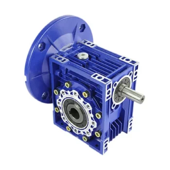
Calculating Gear Ratio in a Worm Reducer
The gear ratio in a worm reducer is determined by the number of teeth on the worm wheel (also known as the worm gear) and the number of threads on the worm shaft. The gear ratio formula for a worm reducer is:
Gear Ratio = Number of Teeth on Worm Wheel / Number of Threads on Worm Shaft
For example, if the worm wheel has 60 teeth and the worm shaft has a single thread, the gear ratio would be 60:1.
It’s important to note that worm reducers have an inherent self-locking property due to the angle of the worm threads. As a result, the gear ratio also affects the mechanical advantage and the system’s ability to resist backdriving.
When calculating the gear ratio, ensure that the worm reducer is properly designed and that the gear ratio aligns with the desired mechanical characteristics for your application. Additionally, consider factors such as efficiency, load capacity, and speed limitations when selecting a gear ratio for a worm reducer.

Materials Used for Worm Gears
Worm gears are manufactured using a variety of materials to meet different application requirements. Some commonly used materials for worm gears include:
- Steel: Steel is a popular choice for worm gears due to its strength, durability, and wear resistance. It can handle heavy loads and is often used in industrial applications.
- Bronze: Bronze offers good lubricity and is commonly used for the worm gear (worm) component. It provides effective wear resistance and works well in applications where quiet operation is essential.
- Cast Iron: Cast iron is known for its high strength and durability. It’s often used for worm gears in applications where shock loads or heavy-duty conditions are expected.
- Aluminum: Aluminum worm gears are lightweight and corrosion-resistant, making them suitable for applications where weight reduction is important.
- Plastic: Some worm gears are made from plastic materials such as nylon or acetal. These materials are often chosen for their self-lubricating properties and quiet operation.
- Composite Materials: Composite materials can offer a combination of properties, such as lightweight construction and corrosion resistance. They can be suitable for specific applications.
The choice of material depends on factors such as the application’s load, speed, operating environment, and required performance characteristics. It’s important to consider these factors when selecting the appropriate material for worm gears to ensure optimal performance and longevity.
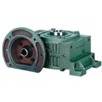
Can a Worm Gearbox Provide High Torque Output?
Yes, a worm gearbox is capable of providing high torque output due to its unique design and principle of operation. Worm gears are known for their high torque multiplication capabilities, making them suitable for applications that require significant torque transfer.
The torque output of a worm gearbox is influenced by several factors:
- Lead Angle: The lead angle of the worm affects the mechanical advantage of the gear system. A larger lead angle can result in higher torque output.
- Worm Diameter: A larger diameter worm can offer increased torque output as it provides more contact area with the gear.
- Gear Ratio: The gear ratio between the worm and the gear determines the torque multiplication factor. A higher gear ratio leads to higher torque output.
- Lubrication: Proper lubrication is essential to minimize friction and ensure efficient torque transmission.
- Material and Quality: High-quality materials and precision manufacturing contribute to the gearbox’s ability to handle high torque loads.
Due to their ability to provide high torque output in a compact form factor, worm gearboxes are commonly used in various industrial applications, including heavy machinery, construction equipment, conveyor systems, and more.


editor by CX 2024-03-03
China wholesaler High Precision RV Cycloidal Industrial Robotics Arm Joint Speed Gearbox Reducer For Servo Motor with Good quality
Warranty: 1 years
Applicable Industries: Manufacturing Plant
Customized support: OEM
Gearing Arrangement: Cycloidal
Output Torque: 65-136N.,m, 65-136N.m
Input Speed: NONE
Output Speed: NONE
Product name: C series LOW BACKLASH RV Cycloid Reducer
Max.Working Torque: 243N.M
Max. Impact Torque: 486N.m
Max.Working Moment: 682N.m
Max. Impact Moment: 1364N.m
Max.Backlash: 1′ arcmin
Tilting Stiffness: 481Nm/arc. min
Torsional Stiffness: 45Nm/arc. min
Weight: 4.8kg
Certification: CE
Packaging Details: Carton with spaom inside the box to protect RV reducer.PE foam and carton for sample RV Cycloid Reducer. PE foam, carton, packing strap and plastic wrap for bulk order of RV Cycloid Reducer.
Port: HangZhou,ZheJiang
High Precision RV Cycloidal Industrial Robotics Arm Joint Speed Gearbox Reducer For Servo MotorSHPR-C is a two-stage gear reducer which consists of the 1st stage of planetary gear reducer and the 2nd stage of cycloidal pin-wheel reducer. The first speed reduction is achieved by the meshing between the big gear of center gear and the planetary gear based on the gear reduction ratio. The planet gear is connected to the crank shaft, Worm Shaft Worm Gear Pair for Transmission Machine and the rotation of crank shaft causes the eccentric rotation of the cycloid disc. This achieves the second speed reduction and thus if the crank shaft rotates 360°, the cycloid disc will rotate 1 tooth in the opposite direction.
Product Features
* With compact structure and high torsional rigidity.* Low backlash (1’ arcmin).* Due to the flexible design of inline component, it can save the mounting space.* RV-E series robot gearbox can support the external load due to the installation of angular contact bearing.* With a high torque capacity, the rated torque can reach to 500%.* Small vibration and long service life.
Working Principle
Product Parameter
Output Speed(r/min)
5
10
15
20
Model
Ratio
Output Torque(Nm)
Input Power(KW)
Output Torque(Nm)
Input Power(KW)
Output Torque(Nm)
Input Power(KW)
Output Torque(Nm)
Input Power(KW)
Motor in Wheel Housing
Motor in Shaft
SHPR-10C
27
26
136
0.09
111
0.16
98
0.21
90
0.25
SHPR-27C
36.57
35.57
368
0.26
299
0.42
265
0.55
243
0.68
SHPR-50C
32.54
31.54
681
0.48
554
0.77
490
1.03
450
1.26
SHPR-100C
36.75
35.75
1362
0.95
1017
1.55
980
2.05
899
2.51
SHPR-120C
36.75
35.75
1422
1.08
1308
1.76
1200
2.22
1085
2.74
SHPR-200C
34.86
33.86
2724
1.9
2215
3.09
1961
4.11
1803
5.04
SHPR-320C
35.61
34.61
4361
3.04
3538
4.94
3136
6.57
2881
8.05
SHPR-500C
37.34
36.34
6811
4.75
5537
7.73
4900
10.26
4498
12.56
Output Speed(r/min)
25
30
40
50
60
Model
Ratio
Output Torque(Nm)
Input Power(KW)
Output Torque(Nm)
Input Power(KW)
Output Torque(Nm)
Input Power(KW)
Output Torque(Nm)
Input Power(KW)
Output Torque(Nm)
Input Power(KW)
Motor in Wheel Housing
Motor in Shaft
SHPR-10C
27
26
84
0.29
80
0.34
73
0.41
68
0.47
65
0.54
SHPR-27C
36.57
35.57
227
0.79
215
0.9
197
1.1
184
1.29
174
1.46
SHPR-50C
32.54
31.54
420
1.47
398
1.67
366
2.04
341
2.38
–
–
SHPR-100C
36.75
35.75
841
2.94
796
3.33
730
1.08
–
–
–
–
SHPR-120C
36.75
35.75
907
3.12
823
3.96
765
4.38
–
–
–
–
SHPR-200C
34.86
33.86
1686
5.88
1597
6.69
–
–
–
–
–
–
SHPR-320C
35.61
34.61
2690
9.41
–
–
–
–
–
–
–
–
SHPR-500C
37.34
36.34
–
–
–
–
–
–
–
–
–
Output Speed(r/min)
Max. Working Torque(Nm)
Max. Impact Torque(Nm)
Max.Working Moment(Nm)
Max. Impact Moment(Nm)
Tilting Stiffness (Nm/arc. min)
Torsional Stiffness(Nm/arc. min)
Max.Backlash(arc. min)
Weight(Kg)
Model
Ratio
Motor in Wheel Housing
Motor in Shaft
SHPR-10C
27
26
243
486
682
1364
481
45
1′
4.8
SHPR-27C
36.57
35.57
660
1320
975
1950
1060
145
1′
8.8
SHPR-50C
32.54
31.54
1200
2400
1750
3500
1940
252
1′
14.9
SHPR-100C
36.75
35.75
2400
4800
2400
4800
2800
505
1′
19.9
SHPR-120C
36.75
35.75
3000
6000
2500
5000
2800
550
1′
21
SHPR-200C
34.86
33.86
4800
9600
8800
17600
9750
960
1′
56.5
SHPR-320C
35.61
34.61
7700
15400
20380
4571
12700
1950
1′
81.5
SHPR-500C
37.34
36.34
12000
24000
34000
68000
24100
3400
1′
160
Application This model high precision RV cycloid reducers are mainly used for medical apparatus and instruments, space, precision positioning turntable, machine tool turret, industrial robot and etc.
Production& Best price HangZhou Advance CZPT brand new marine gearbox JT400A JT450 for ship propulsion engine as clutch Testing
Product details
Company Information
Types of Gearboxes
There are several types of gearboxes. Some are known as helical gear reducers, while others are called planetary gearboxes. The article also discusses Continuously Variable Transmission (CVT) and helical gear reducer. If you are interested in purchasing a new gearbox, make sure to read our articles on these different types. If you are confused, consider reading our articles on planetary gearboxes and helical gear reducers.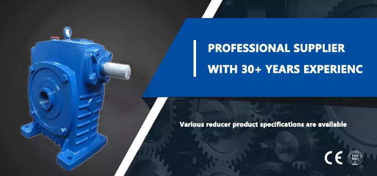
planetary gearbox
The planetary gearbox has several advantages. Its compact design and light weight allows it to transmit high torques while remaining quiet. The gears are connected to one another through a carrier, which is typically fixed and helps transmit torques to the output shaft. Its planetary structure arrangement also reduces backlash and provides high rigidity, which is important for quick start and stop cycles and rotational direction change. Depending on the design and performance desired, planetary gearboxes are categorized into three main types:
The type of planetary gears used in a given application determines the overall cost of the unit. Manufacturers offer a range of prices, and they can help you determine which gearbox is right for your needs. You should also ask a manufacturer for the cost of a planetary gearbox. By asking about price and specs, you can avoid wasting money and time on a planetary gearbox that does not perform up to its potential.
A planetary gearbox is probably installed in your new car’s automatic transmission. For more information, consult your owner’s manual or call the dealer’s service department. This type of gearbox is more complex than other types of gearboxes, so if you don’t know much about them, do an internet search for “planetary gearbox.”
The teeth of a planetary gearbox are formed by the stepping motion of two gears: the sun gear and the inner ring. The sun gear is the input, while the planetary gears rotate around the sun gear. Their ratio depends on the number of teeth and the space between the planets. If you have a 24 tooth sun gear, the planetary gears’ ratio will be -3/2. The sun gear is also attached to the axle.
Another advantage of a planetary gear system is that it can generate high torques. The load is shared among multiple planet gears. This makes the gears more resilient to damage. A planetary gearbox can be as high as 332,000 Nm, and can be used in vehicles and industrial applications requiring medium to high torque. A planetary gear system is a great alternative to a traditional transmission. So, how does it work?
helical gearbox
The main difference between the helical gearbox and the spur gear is the center distance between the teeth. The helical gearbox has a larger pitch circle than the spur gear and thus requires a radial module. In addition, the two types of gears can only be made with the same tooth-cutting tool as the spur gear. However, the helical gearbox is more efficient in terms of production costs.
The helical gearbox is a low-power consumption, compact type of gearbox that is used for a wide range of industrial applications. They are highly durable and withstand high loads with utmost efficiency. The helical gearbox can be manufactured in cast steel and iron for small and medium units. This type of gearbox is also commonly used for crushers, conveyors, coolers, and other applications that need low power.
The helical gear has many advantages over the spur gear. It produces less noise. It has less friction and is less likely to wear out. It is also quieter than spur gears. This is because multiple teeth are in mesh. Because the teeth are in mesh, the load is distributed over a larger area, resulting in a smoother transition between gears. The reduction in noise and vibration reduces the risk of damaging the gear.
The helical gear’s axial excitation force is obtained using a linearized equation of motion in the rotational direction. The damping coefficient of the equation is 0.07. The helical gear is made up of a steel shaft with a diameter of 20 mm and a 5 mm thick aluminum plate. The stiffness of the bearing is 6.84 x 10⁷ N/m. The damping force of the plate is 2,040 kg/m2/s.
The worm gearbox has a better efficiency ratio than the helical one, but it is less efficient in low-ratio applications. In general, worm gearboxes are more efficient than helical gearboxes, although there are some exceptions to this rule. A helical gearbox is better for applications that require high torque. It may also be more economical in the long run. If you are considering a helical gearbox, consider the advantages it has over worm gearboxes.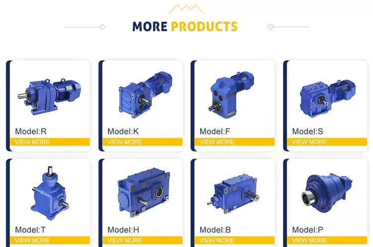
helical gear reducer
A helical gear reducer for a machine’s gearbox is an integral component of the drive system. This unit amplifies torque and controls speed and, therefore, compliments the engine by rotating slower than the engine’s input shaft. A helical gear reducer is a compact gearbox component that is used in industrial applications. A variety of sizes is available to suit various machine configurations. The following sections will discuss some of the different types available.
Designed by experts and engineers, a helical gear reducer is a surprisingly small and light gear that satisfies the needs of many machine applications. It features a large transmission torque, a low starting and running speed, and a fine classification of transmission ratios. A helical gear reducer is lightweight and easily connected to other gears, and it features a high technical content.
In order to avoid errors and poor performance, regular maintenance is a must. The proper lubrication of the gear reducer can minimize failures, errors, and poor performance. Every gear reducer manufacturer sells a suitable lubricant, which must match the properties of the machine’s drive mechanism. It is also advisable to check the lubrication regularly to avoid any deterioration of the unit’s performance.
While the worm gearbox may be better for applications where torque is high, the helical gear reducer offers greater efficiency at lower cost. Although worm gearboxes may be cheaper initially, they are less effective at higher ratios. Even if the worm gear is more expensive to buy, it still offers 94% efficiency, which makes it more cost-effective. There are some significant advantages to both types of gearboxes.
The main advantage of a helical gear reducer over a spur gear is its smoother operation. Unlike spur gears, which have teeth that are straight, helical gears have angled teeth that gradually engage with each other. This helps ensure that the gear does not grind or make excessive noise when it turns. Additionally, they are less commonly used in automation and precision machinery. They are often used in industrial applications.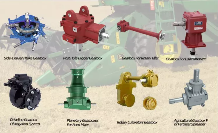
Continuously variable transmission
A Continuously Variable Transmission (CVT) is an automatic transmission that can run through a vast number of gears. Unlike a standard automatic transmission, it can run at any speed, even at a low rev. The CVT is also capable of running at infinitely low gears. Its basic function is to provide different torque ratios to the engine. In addition to delivering power, CVTs have other benefits.
One of the major advantages of a CVT is its simplicity. Its simplicity translates into fewer moving parts, which means less maintenance. The CVT’s simplicity also means that it can handle a wide variety of different types of road conditions and driving styles. In addition to being a great alternative to a traditional automatic transmission, CVTs can be used on many other types of vehicles, including tractors, snowmobiles, motor scooters, and power tools.
A CVT is much smoother than a conventional automatic transmission. It never has to hunt for a gear. It also responds well to throttle inputs and speed changes. Both of these technologies are available on many modern vehicles, including the Nissan Rogue and Mazda CX-5. It’s important to note that each of these transmissions has its pros and cons. So, if you’re looking for a car with a CVT, make sure to read the reviews. They’ll help you decide which transmission is right for you.
Another advantage of a CVT is its fuel efficiency. Many cars now feature CVTs, and they’re becoming increasingly popular with automakers. In addition to fuel efficiency, most cars with CVTs also have a smoother ride. There’s no more sudden downshifts or gear hunting. This makes driving a lot easier. And, the added benefits of smoother driving make CVTs the ideal choice for many drivers.
Although a CVT is more common among Japanese car manufacturers, you’ll find CVTs on European car models as well. The Mercedes-Benz A-Class, B-Class, and Megane are some examples of vehicles that use this technology. Before making a decision, consider the reliability of the model in question. Consumer Reports is a good resource for this. It also offers a history of use and reliability for every type of car, including the Honda Accord.

